MKS 937B Half-Rack Combination Controller, Operates up to Six Vacuum Pressure Sensors Simultaneously, NO Cards, RS232 and RS485 (built in).
MKS Part Number: 937B-US-NANANA-NA.
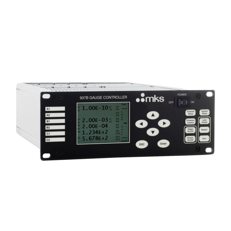
The MKS 937B Digital Combination Vacuum Gauge Controller operates up to six vacuum pressure sensors simultaneously. This highly flexible vacuum gauge controller supports a wide range of sensor technologies, including cold cathode, hot cathode, standard Pirani, convection Pirani, Baratron® capacitance manometers and absolute Piezo sensors for a measurement range from ultra-high vacuum to above atmospheric pressure.
The 937B controller is designed for versatility, reliability and economy. The large, easy to read, liquid crystal display provides readout for up to six sensors simultaneously. The back lit LCD display, intuitive menus and simple push button front panel, allows for ease in setup of the 937B. This controller enables the use of any sensor card in each of the sensor card slots. The 937B can be configured with up to three hot or cold cathode type gauges, or three dual sensor cards for a maximum of six gauge connections.
Set Points: Twelve independently adjustable set points are standard. This allows for the automation of process related functions. The set point values are nonvolatile and remain unchanged after power down or power failure. They are easily viewed and configured in the channel set up screen. The 937B also includes an adjustable control set point that turns the cold cathode or hot cathode gauges power off or on, at the desired pressures, extending the sensors life.
Leak Test: The leak test mode includes a bar graph and variable audible alert to assist in locating leaks within a system. The function operates with the cold cathode, hot cathode, Pirani, and convection sensors. By taking advantage of differences in tracer gas sensitivity, this provides an excellent tool for helping locate coarse system leaks.
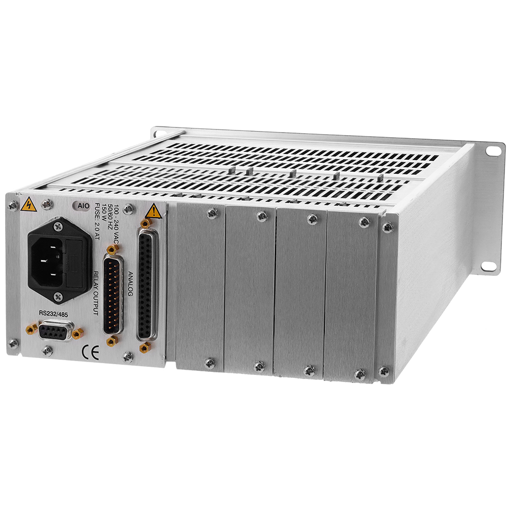
Analog Output Signals: The controller provides analog output signals accessible on the rear panel connector. Three types of analog signals are available. Unprocessed analog signals are used to provide the fastest response times. The logarithmic output voltages are scaled so that 0.6 Volts equals one decade of pressure. Combination output can be created by combining up to three sensors with a combined range from 10-11 to 20,000 Torr.
Digital Signals: In addition to analog outputs, the 937B communicates digitally for direct computer communication with built in connections for RS232 or RS485. A communication slot in the 937B chassis accepts an optional Profibus DPV1 board. The 937B can communicate with a host computer using either of these ports. Remote control of set points and cold cathode high voltage disable are some of the many features available with communications options. Signal cables and optional cards for the MKS 937B are available on this website.