Matheson Model 18 Single Stage General Purpose Brass Regulator
SEQ18, CGA-326
A CGA fitting is the standardized system for the attachment of a compressed gas cylinder to the required regulator or transfer line. The three digit number, CGA (XXX), corresponds to specific gasses which that fitting is tailored for.
See CGA Connection Chart.pdf in the downloads section for specific gas types compatible with this Nickel Plated Brass CGA-326 fitting.
Regulator Specifications
- Maximum Inlet Pressure: 3000 psig (20,700 kPa)
- Maximum Flow Rate: 2000 CFH (944 LPM)(At 2000 psig, N2)
- Flow Capacity (Cv): 0.17 (without outlet valve)
- Operating Temperature: -20°F to 140°F (-29°C to 60°C)
- Porting (Regulator Body): 1/4 NPT Female
- Porting Configuration: 2 High, 2 Low
- Delivery Pressure Range: 2-50 PSIG
- Delivery Pressure Gauge: 0-60 PSIG
- Cylinder Pressure Gauge: 0-4000 PSIG
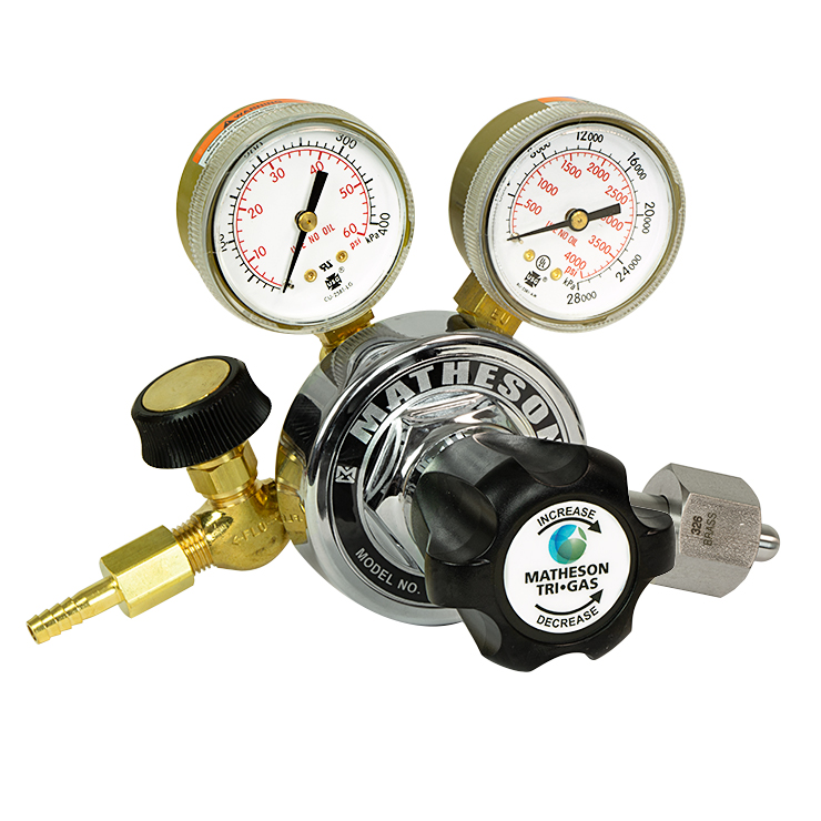
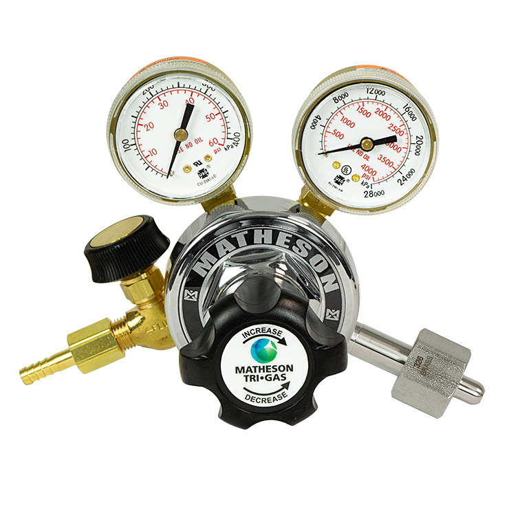
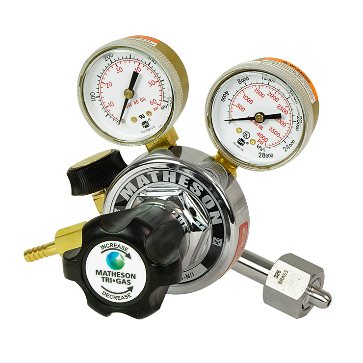
This is a Matheson Single Stage Brass regulator with a 1/4 in MNPT outlet connection (with loose 1/4 in hose barb) and 1/4 in FNPT body porting. It comes equipped with 2 inch inlet and delivery pressure gauges, outlet needle valve, Neoprene seals, chrome plated brass bonnet, and a PTFE Teflon seat.
This Matheson series 18, model 18 regulator is to be used in applications requiring delivery pressures up to 50 PSIG and can accept a maximum inlet pressure of 3000 PSIG. This regulator is suitable for a variety of applications that require gasses that are 99.995% or lower purity. This regulator is not suitable for any application requiring the supply of corrosive gas (non-corrosive gas applications only).
Single-Stage vs. Two-Stage
Both single-stage and two-stage regulators operate by reducing the pressure of gas supplied by a cylinder to an appropriate output level. The intake and delivery pressure ranges of regulators do not depend on how many stages they have, but by each regulators mechanical characteristics. When considering a single vs. a two-stage regulator there are two things to keep in mind: Droop and Supply Pressure Effect. Droop is the decrease in output pressure caused by an increase in flow rate. Supply Pressure Effect is simply the variation in delivery pressure from the cylinder to the regulator.
Single Stage regulators will experience less droop with varying flow rates but a large supply pressure effect and need to be monitored and adjusted by an operator or used in applications where supply pressure will remain constant. Two-Stage regulators inherently control for variations in supply pressure while producing a constant output and therefore can be used without an operator present and in applications which require a very specific delivery pressure. The specification sheet for this series of regulator can be found in the downloadable section as a .PDF.